UPDATED 2014.06.15 Important Note: I discovered that the usage of the function pwm.setservo() it is not adeguate to control the motor in a loop. Everytime it is called, it sets the pwm to zero than it sets the new value. the result is a loss of speed (and so power ) of the motor. I just start to use the pwm.add_channel_pulse() instead and it solve the problem.See motor.py for the last version of code.
Last Saturday it was the great day: first brushless moved! And moved with rpi!!!
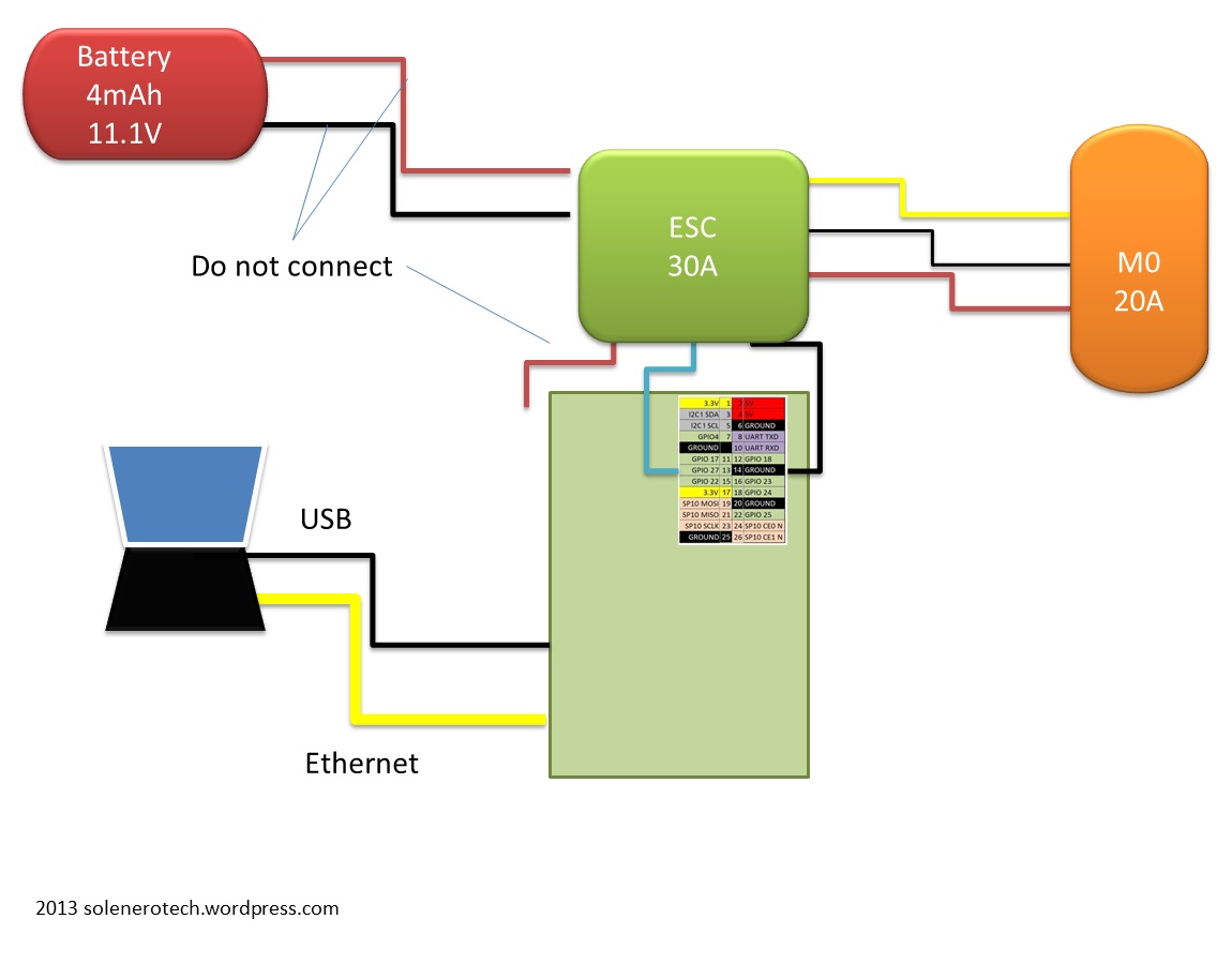
Right now I prefer not to mix up too much things, so the rpi is powered via usb and the connection is done by ethernet cable.
Those the details for the necessary steps.
- Mount the motor firmly. IMPORTANT: Remember it will move,so fix it well!
- Connect the motor wires to the esc.my motor has got 3 cables:red,black and yellow.I decided always to connect the black on the middle, and i can invert yellow and red to change rotation side.
- Do NOT connect yet the esc power cable to the battery
- Connect esc 0v signal (black) to th rpi ground (for example pin 25)
- Connent PWM signal(white) on a rpi output.In my example i connect on pin 11 called GPIO17. This value(17) is used in the program.
- Connect Ethernet cable
- Connect USB to power on rpi


Let’s see now the software. It is necessary to install on rpi the RPIO library.You an find how to do it in the SW installation post.
- Donwload the motor_test folder tha includes motor_test.py and motor.py and copy in home/python/motor_test on your pc.
- On the pc terminal copy the folder on rpi: (it is requred the rpi password):
scp -r python/motor_test  pi@10.42.0.63:./python
password : raspberry
- On the pc terminal run the command to connect to rpi.now the terminal is the rpi terminal.
ssh pi@10.42.0.63
password : raspberry
- Finally run the motor_test program.Important: the startu sequence of an ESC can vary by the model.See the ESC page for details.
cd python/motor_test
sudo python motor_test.py
- Follow the program instruction.

After the first ENTER , the PWM signal is set to the maximun value (a pulse width= 2000us every 20ms).Now you can connect the ESC power cables.If everything goes right (correct voltage, cell number correct) ESC is ready to pilot the motor.PWM signal goes to 1000us,the minimum value.So it is possible to play with the motor speed.My motor starts to move over 5%,it means 1050us.This value depends from motor inertia from friction and from battery charge level.

Hi,
I am as well working on similar project. I tried to control using servoblaster (https://github.com/richardghirst/PiBits/tree/master/ServoBlaster) ended up with a blown motor. Before I did a trial run using a servo successfully connected directly to the PI. I don’t have a clue what went wrong with brushless motor. Before attempting to try again, I would like to get some advice.
I am thinking 50 Hz signal is very low for ESC/brushless motor. It seems the ESC I am using requires minimum 8k Hz. Is that true? Motor juddered first and then died emitting smoke.
http://www.hobbyking.com/hobbyking/store/__15205__Hobby_King_30A_ESC_3A_UBEC.html
Now I am thinking of trying with this library as I can set the PWM frequency to 8k Hz.
http://abyz.co.uk/rpi/pigpio/
Any response is much appreciated.
Thanks,
Hello ,
Take a look to my blog paga dedicated to ESC : https://solenerotech1.wordpress.com/esc/
There is a desciption about the pulse .
Let me know in case you need more suggestions
hi gk, I checked yuor esc manual.
The 8khz that you are referring is the frequency from ESC to the motor.
The 50hz frequency is the command pulse, from RPI to ESC
Hi,
Thanks for taking time to look at my issue and explaining about the frequency. I had some success in the weekend, now getting correct beep responses from the ESC, but still no movement.
Thanks,
Hi,
I am trying with GPIO4.
Thanks,
I also had no movement until i increased the signal over 5% . Have you tried?
Yes, I did increase it to 10%. No movement, will try again in the weekend.
Thanks,
Hi,
Just to update you, mine worked at 13%.
Thanks
Good to know!
good luck
Oscar
I got a problem when i run the program.. Python tells me that the function cycling issn’t correct.. by the while cycling… Can some one help me with this problem?
Hi matthijs,
I double check the code and I cannot find any error.
Cycling is not a function, but a boolan variable used for testing the while loop.
I’m not an expert in phyton. Maybe there is some conflict in your sw installation.
Maybe there a naming conflict. try to change “cycling” with “cycling_1” in all the code.
Salve,
vorrei realizzare un progetto simile con raspberry. Vorrei che il mio raspberry generasse una rete ad hoc wifi e creasse una pagina web attraverso la quale io da terra posso avere pieno controllo. All’inizio avevo pensato di utilizzare Arduino(che ho già utilizzato per altri progetti) ma ho riscontrato grandi difficoltà nel creare una rete ad hoc(senza router quindi, condizione necessaria per utilizzare il quadricottero all’aperto)visto che i shield presenti sul mercato non consentono questa possibilità.
Venendo al dunque, il raspberry mi sembra il controllore più adatto, ma non avendo esperienza con gli ESC mi sorge un dubbio. Le porte GPIO del rasp funzionano a 3.3V. Come è possibile dare un segnale di controllo per un motore da 5V?
Quando ho provato ad utilizzare raspberry per controllare due motori attraverso l’integrato LN298n il massimo segnale che potevo dare in uscita era a 3.3V, e quindi ottenevo il risultato atteso: i motori giravano piu lenti rispetto a 5V. Qui non avrei lo stesso problema?
Grazie mille
l esc regola la velocita del motore in funzione della lunghezze degli impulsi che riceve e non in funzione della tensione. Poi potrei essere smentito da un elettronico…
Ho comunque letto di quadricotteri in cui usano arduino per il controllo motori e raspberry per la parte di comunicazione e comando facendo dialogare i 2 device
Ps. In uno deglu ultimi post trovi esempio di webserver che e’ la base di lavoro per pilotare il drone da qualunque device dotato di browser
Si anche se preferirei utilizzare solo Raspberry.
Tu (mi permetto di darti del tu) con questo progetto sei riuscito a pilotare tranquillamente l’ESC con raspberry e riesci a sfruttare al max il motore?
Perchè almeno per quanto riguarda il motore in DC standard con L298N la velocità dei giri va in base alla tensione, e il raspberry dando 3.3 sulle GPIO chiaramente fa girare piu lentamente il motore…
Nessun problema. La potenza al motore e’ data dall esc. Raspi invia solo un segnale d pilotaggio
Ok, ultimo commento e poi non disturbo più….ma il segnale di controllo non dovrebbe esser comunque proporzionale alla tensione applicata? chiedo perchè sono molto dubbioso, e prima di fare un acquisto affrettato vorrei capire bene se questo è un problema reale….se comunque tu sei riuscito a farlo funzionare seguirò una tua guida
cioa, mirko, ho verificato sul foglio d’istruzione dell’ESc. nelle specifiche non ci sono indicazioni di voltaggio specifiche. Si dice solo di collegare il segnale al “reciver”. andrebbe cercato a che voltaggio lavora unreciver standard per un aeromodello.
ad ogni modo il controllo non viene fatto in base alla tensine ma in base alla lunghezza (in tempo) di ogni impulso.
qui trovi una breve descrizione.
Ciao solenero, confermo. Anche io mi sono documentato in questi giorni, effettivamente l’ESC sembrerebbe funzionare unicamente grazie alla PWM…..quindi per adesso sono riuscito a creare una rete ADHOC con l’adattatore wifi(non ho più bisogno del router di mezzo quindi, ho utilizzato un TPLINK WN725N) e sto creando con apache un web server…poi passerò alla parte pratica dei motori.
Grazie
Ok. Magari sulla parte web server ti chiedero’ io qualche dritta.
Buon divertimento
Hey solenero, sulla parte PWM mi hai convinto, anzi ti vorrei chiedere una cosa: sulla libreria PWM come controlli il motore? scrivi PWM.(numeropin,frequenza)? se si, da dove hai studiato come funziona la libreria? purtroppo sul PWM sono un po digiuno…
piuttosto sono riuscito a creare una rete ad hoc, di nome raspberry, alla quale mi connetto come se mi connettessi ad una semplice rete wireless, vado sul localhost e mi viene mostrata la pagina che è creata da apache…..ho scritto un html con immerso un po di php…per adesso ho creato due bottoni che accendono e spengono un led…quindi il php fa una chiamata a due script python….però ho riscontrato un problema non banale….la latenza!!!!!!!!
Ogni volta lui deve ricaricare la pagina, il che potrebbe esser un problema poi sul quadricottero!Tu come pensavi di risolvere? io pensavo che forse si potrebbe adottare AJAX, anche se ancora non sono molto pratico….
ciao
Ho gia caricato in un post un mese fa circa un mio esempio base di webserver ad hoc. Non lo sto usando pero’ ora x comandare quadc.
Per il motore, trovi spiegazione e codice nel menu python>motor.py
I was wondering how to control 4 ESCs with the Pi using least amount of GPIO pins as possible. Is it possible to connect the four ESCs in parallel ?
And also what do I need to do if I want to send different PWM signals to the four ESCs
Any help would be appreciated 🙂
Souvik, take a look on my post sw installation where it is described the rpio library that allow you to use any io as pwm.
Thanks 🙂
Hello Souvik ,I just published a post with the code example called beta1 where you can see how I manage the 4 motors
Thank you. It was indeed concise and helpful.
Hi,
Do you know how to reverse the direction of the motor? In your later tests how did you get the correct rotational direction of the propellers so it could fly?
Thanks
Hi
Just reverse 2 of the 3 wires between Motor and esc. No matter which ones.
Awesome thanks
Hey, i have A2212/13T brushless motor and Emax Simon Series 25A Esc. I have tried a lot to get the beeps, eventually i got the beeps but when i used your program than nothing happened. Please help me with the connections of ESC with raspberry Pi gpio pins. Please mail me your email id so that i may reach you instantly
Hello Ankur,
I didn’t get one point on your description, what do you mean with “eventually i got the beeps ” .
Using my example? Could you add a print scrren of the point where you get stock?
Generally if you get the 3 beep, than using the keyboard you can control it: a to increase the throttle, z to reduce it.
Note that the minimun value to start the motor depend mainly on your hw
Hi there. I got the BLDC running. I have RPI 2. There is no support for RPIO in RPI 2. I am now using RPi.GPIO for PWM. Writing my own code for it. Problem is motor starts then it gains some speed and then stops. Again it starts and stop…..same thing happens again and again. Is there a solution for it?
Sorry but i cannot help you on this topic.
Hi , when i start motor_test.py i have this line “usage: motor_test.py [-h] [-i] gpio” followed by this line “motor_test.py: error: too few arguments” , please what could be the problem ? i have installed RPIO and made everything on the tutorial …
Hi Ali,
You miss an argument when you run the example.
it is mandatory to define which pin of the rpi you want to use to control the motor.
For example, if you connect the motor with pin 12 , equal to GPIO18 you need to run : sudo python motor_test.py 18
Hi,
When I run motor_test.py using “sudo python motor_test.py” after pressing enter for the second time after “***wait beep-beep ***then press enter” I get
“Traceback (most recent call last):
File ‘motor_test.py”, line 28 in
res = raw_74input()
NameError: name ‘raw_74input’ is not defined”
Any idea what is causing this issue?
Thanks,
Mial
Ignore this was using out of date code
What have you done to fix this problem?
I have the same
Hi as I wrote I used the add_ cchannel_pulse() function instead of setservo()
Hi!
What is the ESC 5vfor? (the red one connected to the battery not, the other one).
It works without connecting that cable.
Thanks!
Hi Solenero!
This is quite possibly the most helpful page I have encountered in relation to quadcopters and Raspberry pi. Thank you for the posts.
My question: When I run my code, I get an error that states the object ‘motor” takes no parameters for the line of code motor(‘m1’, gpio, simulation = False). er
If I remove the parameters, the code goes to the next stage then crashes. (This is expected as we need the parameter simulation = False)
How do I rectify this error?
Try to run motor_test 18
Where 18 is the gpio used to pilot Your Motor.
Oscar
Hi solenerotech. Thanks for the great post! I am worried about the logic level of the ESC. I am using a RPi v2 with Flycolor 20A Simonk ESCs. Not sure if these ESCs respond to PWM of 3.3V level.
I have been trying to find this info, but no luck so far. I will be very grateful for any help you could give me here.
Thanks!
Hi Jonnie. Did you solved your problem?
I woul dsay that it shold work at 3.3V .
solenero,
I have put your code onto my Rpi and when I try and run the test code i get this:
pi@raspberrypi ~ $ sudo python motor_test.py
Traceback (most recent call last):
File “motor_test.py”, line 8, in
mymotor = motor(“m1”, 18, simulation=False)
File “/home/pi/motor.py”, line 39, in __init__
from RPIO import PWM
File “build/bdist.linux-armv7l/egg/RPIO/__init__.py”, line 115, in
File “build/bdist.linux-armv7l/egg/RPIO/_GPIO.py”, line 7, in
File “build/bdist.linux-armv7l/egg/RPIO/_GPIO.py”, line 6, in __bootstrap__
SystemError: This module can only be run on a Raspberry Pi!
can you PLEASE help?
Hello Dominic, it seem a release issue: see the discussion on raspberry forum: https://www.raspberrypi.org/forums/viewtopic.php?t=98466
solenero,
when i use the code provided on my rpi i get the following:
pi@raspberrypi ~ $ sudo python motor_test.py
Traceback (most recent call last):
File “motor_test.py”, line 8, in
mymotor = motor(“m1”, 18, simulation=False)
File “/home/pi/motor.py”, line 39, in __init__
from RPIO import PWM
File “build/bdist.linux-armv7l/egg/RPIO/__init__.py”, line 115, in
File “build/bdist.linux-armv7l/egg/RPIO/_GPIO.py”, line 7, in
File “build/bdist.linux-armv7l/egg/RPIO/_GPIO.py”, line 6, in __bootstrap__
SystemError: This module can only be run on a Raspberry Pi!
can you help?
Hello Dominic, it seems a problem on rpio library. I fuond this forum discussing the same issue: https://github.com/metachris/RPIO/issues/53
Hey solenerotech, I got this message when I try to run motor_test.py
I tried the suggested solutions in the links you gave to Dominic, but it still doesn’t work
pi@raspberrypi:~/PopciQuad $ sudo python motor_test.py 17
gpio: 17
initEsc: False
Traceback (most recent call last):
File “motor_test.py”, line 56, in
mymotor = motor(‘m1’, gpio, simulation=False)
File “/home/pi/PopciQuad/motor.py”, line 53, in __init__
from RPIO import PWM
File “build/bdist.linux-armv7l/egg/RPIO/__init__.py”, line 115, in
File “build/bdist.linux-armv7l/egg/RPIO/_GPIO.py”, line 7, in
File “build/bdist.linux-armv7l/egg/RPIO/_GPIO.py”, line 6, in __bootstrap__
SystemError: This module can only be run on a Raspberry Pi!
Please help me!
Actually I figured out a way to fix it using tylerwowen’s patched version of RPIO in the second link you gave to Dominic, but now the problem is the esc doesn’t seem to be connecting to the pi. I put the program on, followed the instructions, but when it comes to the “beep for number of cell” part, the motor beep infinitely and never actually go “beeeeep”. I am using a Turnigy Plush 25A ESC with the Scorpion M‑2204‑2300KV brushless motor. Please help me if you can!
Which rpi version are you using?
Hi there,
I’m running into the following trouble:
root@raspberrypi:~# python motor_test.py
Using hardware: PWM
PW increments: 10us
***Disconnect ESC power
***then press ENTER
Initializing channel 0…
Traceback (most recent call last):
File “motor_test.py”, line 15, in
mymotor.setW(100)
File “/root/motor.py”, line 133, in setW
self.__IO.set_servo(self.__pin, PW)
File “/usr/local/lib/python2.7/dist-packages/RPIO-0.10.0-py2.7-linux-armv6l.egg/RPIO/PWM/__init__.py”, line 212, in set_servo
File “/usr/local/lib/python2.7/dist-packages/RPIO-0.10.0-py2.7-linux-armv6l.egg/RPIO/PWM/__init__.py”, line 97, in init_channel
RuntimeError: rpio-pwm: Page 0 not present (pfn 0xa100000000015d2b)
Does anybody have the same error?
Any help would be much appreciated.
Cheers,
Bastian
I did some research now.
My dmesg contains the following entry:
BCM2708FB: allocated DMA channel 0 @ f3007000
Might it be, that channel 0 is used by the Framebuffer, and cannot be used for PWM?
Cheers,
Bastian
Hi bastian, I do not know how frame buffer works. But if you suspect a conflict on Duma channel, just change it.
Oscar