Monthly Archives: February 2016

myR: The Pi Camera p2

camserver and CamHandler

in order to stream the video on a  browser , I add this camserver object that it takes care to pass the last available image.

Consider this webserver is working on port 9094, You can easily test it by  run:

sudo python camera.py

than typing on a browser:

http://192.168.0.10:9094/image.mjpg

Cam4

and (you need to close the previous page first)

http://192.168.0.10:9094/mask.mjpg

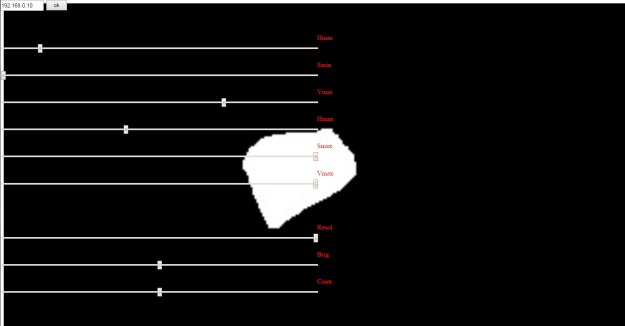
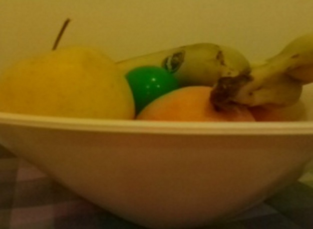
They are respectively the last image with result of ball tracking and the result of the filters before search for the contors.

This can help to define which values of HSV are correct to look for green color.This part can be quite tricky, so I created also a html page that can help me by moving slides on it.You can open it in the browser but for the moment it does not apply the change on the mask (this will work only when I will introduce also the server.py and the rc.py -remotecontrol- in the future posts).

Cam3

In my github you can find now the upload of this part of the code.

PS: Note that now there is a bug that I did not yet solved: since in the camHandler.do_GET there is an infinite loop continuously updating image, you can not open two pages  connected to the same server.You need first to close a webpage than open the new one.


myR: The Pi Camera

The Pi camera is an argument that can take some posts.

The hw installation has been pretty simple , also for me.I follow the indications reported in the  https://www.raspberrypi.org/help/camera-module-setup/   and https://www.raspberrypi.org/documentation/usage/camera/README.md.

Then  I tested it worked using raspivid: https://www.raspberrypi.org/documentation/usage/camera/raspicam/raspivid.md

So, ready to develop my camera.py class.

Requirements are:

  • stream images on a browser
  • recognize  items in the image (ball tracking, as first attempt)
  • stream the result in the browser
  • run the camera code in a parallel thread

My camera.py module  includes 4 objects (classes):

  • camera: dedicated to collect images from camera and elaborate this information, in particular  performing the ball tracking feature.
  • camserver : used to serve the images to the browser.It control the camHandler
  • camHandler: the webserver class that pack data and return it to browser.
  • camera_data: the class including the data to share ( camera parameters , results, images.


camera(threading.Thread):

It first inits the camera by :

self.camera = picamera.PiCamera()

Then it is possible to start the man loop of the camera by   camera.start().

This loop include  a call to :

  • the procedure  self.configure(). Here it is possible set up the camera parameters by writing a command in the variable  self.data.config. It is useful  for tuning the thresholds for  colors during the  ball tracking.
  • the self.camera.capture(rawCapture, format=’bgr’, use_video_port=True). It just the the picture
  • finally the self.balltracking(image). where it is done the balltracking and returning some information, for example the position of the ball in the image and the estimated distance of the ball respect the rover.


The balltracking is obtained by  using the famous openCV  library: http://docs.opencv.org/2.4/

In order to install this library I found quite a lot complicated  posts googling around, finally I decide to follow this raw method , that worked (at least for me):

sudo apt-get install python-numpy
sudo apt-get install python-scipy
sudo apt-get install python-imaging
sudo apt-get install libopencv-dev
sudo apt-get install python-opencv

The ball tracking  is also a well known  exercise. I used this blog  to start my dev: http://www.pyimagesearch.com/2015/09/14/ball-tracking-with-opencv/


Cam1

Summing up, the image is first filtered.

Then I decide to search for a green ball, so I setup my HSV parameters (I’ll show how later).

The image than become a black and white image: all the pixel inside my HSV thresholds are set to black , all the rest are set to white.

With cv2.findContours(…)  you can get a list of contours of the “black items” in the image.So , look for the biggest one ( I suppose in the image there is only one green item: my ball), find its center calculate its radius, and estimate the distance (by a proportion). Finally add some info and draw some lines.Done!

Cam2

In the next post I’ll explain how to expose the images on the web and how to find the right  thresholds for Hue , Saturation and Value (HSV).


myR: ultrasound sensor

The ultrasound sensor is used to measure the distance respect an item in front of it.

A basic ultrasonic sensor consists of one or more ultrasonic transmitters (basically speakers), a receiver, and a control circuit. The transmitters emit a high frequency ultrasonic sound, which bounce off any nearby solid objects. Some of that ultrasonic noise is reflected and detected by the receiver on the sensor.

WP_20160212_002

There are a bounce of tutorial on how to use it.I  just follow this perfect tutorial :

www.modmypi.com

In this post I want to focus the sw code I developed and I just post the wiring:HC_SR04_2

The module is called us_sensor.py and it is upload in  Github>>myRover.

Inside you can find an class object called us_sensor_data, that collect the information to share with the world (the distance in [mm] and the period of  measurements in [sec].

This choice to create a separate class will become very useful when I will put all togheter (in the rover.py). In this way any  object can see all the information from other objects.


The main class  is the us_sensor  object.

def __init__(self, name, trigpin, echopin, data):

Where you need to pass a name, the GPIO pin for the trig signal (output) and the GPIO pin for the echo (input) signal.

This object  works in a parallel thread (threading.thread), so while in your main loop you can do something, the us_sensor continuously (every data.period time) measures the range and put this information in data.distance.

Since it is parallel thread you need to start it first,by calling  mySensor.start(). This call recalls then the run(), where there is the measurement loop.

Then you need to stop it when closing the application , and mySensor.stop().

Note that if you have more threads running  the measurements become less precise.

In addition if an item is very close to the sensor it happens to loose some echo signal.In order to avoid the loop to freeze waiting for a signal that was lost, I manege also a timeout.

Finally you can find a main()  to test the sensor by itsself.

#init data class
data = us_sensor_data()
#init sensor
mySensor = us_sensor('HC_SR04', 4, 17, data)
mySensor.start()
#from this moment the sensor is measuring and puts the result in mySensor.data.distance
...
while mySensor.cycling:
     #here do something...
     ...
     #than get the info when you need it
     s = 'Distance: ' + str(mySensor.data.distance)
     ...
finally:
# shut down cleanly
...
mySensor.stop()


myR: How to control DC Motor part3

This 3rd part is dedicated to the sw .

I use an approach object-oriented, so I prefer to create for each real component a equivalent sw  class object. It means that I try to include in the code all the parameters necessary to describe the item and its behavior.

The advantage of this approach is that if I need 20 motors, I just initialize 20 istances of my DCMotor Class.

The translation of this concept is very simple:Which parameters can describe can describe my motor?

The fundamental information is:  which is its speed? and than which are the limits of this speed?

Again, How phisically can control the motor, so which pins are used to set the speed?

All of this information are included in the init() of my class:

def __init__(self, name, MBack, MForw, channel1, channel2, WMin=-100, WMax=100, Wstall=30, debug=True,simulation=False):

MBack is the GPIO pin used to move the motor Backward, channel1 is the DMA channel used for it.

MForw is the pin for motor Forward. channel2 is the DMA channel used for it.

Wmin and Wmax is intuitive…

WStall is the  minimun speed that cause the motor not to move.

The actions that can be done onmy motor are:

1)Start the motor – in reality this just initialize the GPIO channels and pins.

def start(self):

2)Stop the motor – stop the GPIO channel.

def stop(self):

3)Set the speed W – check the speed is inside the limits,check if the motor is requested to move backward or forward , reset the unsued pin and set the pulse width of the correct pin.

 def setW(self, W)


Finally  by calling in a main routine those functions you can move your motor:

myDCmotor = DCmotor('myMotor', 18, 23, 11, 12)
myDCmotor.start()
myDCmotor.set(30)
#accelerate
myDCmotor.set(80)
#deelerate
myDCmotor.set(50)
#move backward
myDCmotor.set(-40)
#brake
myDCmotor.set(0)
#stop
#myDCmotor.stop()

You can download the code from Github-solenerotech/myRover

NOTES:During the programming , also when I added other devices like picmaera and ultrasound sensor I notice some bad behaviour on the GPIO system.For this reason you can find in the code some choices that are explained by this problems.

1)I notice that it is necessary to use one channel for each pin. Otherwise the pulse width is inverded ( if I set W=90% it runs 10% ans so on).  Thats expalin channel1 and channel2.

2)the DMA channels are used to create the PWM. But the DMA channels in rpi are used also for other activity. So you need to avoid some of them, in particular DMA channel 0  is used for the system and DMA channel 2 is used for the sdcard. So avoid those 2 channels.

3)In order to generate a PWM you can use hardware clock or sw clock. The hw clock is used also by Picamera, so this can generate an interference to the picam itself. To avoid this I’m using the sw clock on the PWM. This is obtained by using in the PWM setup the option delay_hw=PWM.DELAY_VIA_PCM