Category Archives: testing

myQrc – test completed

I just upload the last and final version of the myQ release candidate on github

DSC_6918

All the software has been debugged and  tested.

All the functionalities are now stable.

I tested in different options (debug mode, netscan activated, sensor log)  and the result is that I can run the main loop every 10 ms and  get sensor data every 6 ms.

It can happen to have a delay on the  sensor data loop  when a log is added ( 2/3 ms).


I removed the webserver from the list of test to do, so it is not supported in this version of the software. The main reason is an instability when runnin gon raspberry. I have to investigate a more robust way to manage the comunication via browser.


Next time I will write a post the drone will be just landed…(after its first flight!!!)

Beta1test. Bugs and a steps ahead

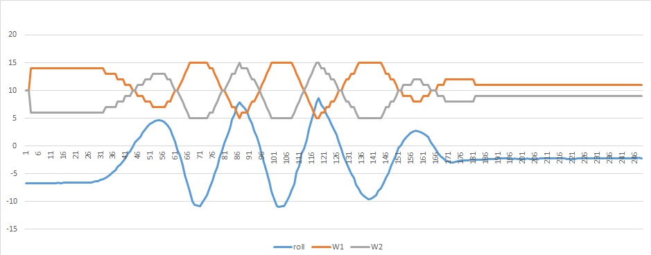
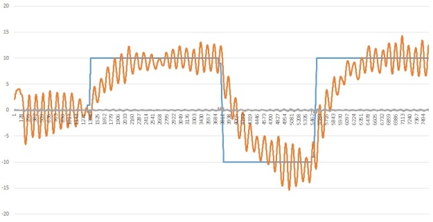
Yesterday I got this result:

beta1_graph1

Thanks to the following actions:

1)The test with the ball on the bottom of the drone,did not convince me. the friction on the ball, the  rotation limits due to the basement, were all components that are not present during the flight.

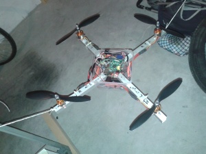
So I decided to switch to the more used and recognized  solution with the quadcopter tied up with 2 wires.

beta1_tied_up

2) I realized  that something was wrong on the motors behaviour.When I  run the beta1.py   the motor sound  was unstable and unconstant evenif  I was not  controlling it with PID ,just make them run in throttle speed.

This is not happening if I run the motor_test.py.

Finally I was able to reproduce the problem and I realized there is a bug (or better an unexpected behaviour)  in the  library RPIO. If I run this loop (that reproduces the main loop of the beta1) I got the unstable motor rotation:

while true:

mymotor.servo.set_servo(self.pin, PW)

sleep(0.01)


My explanation is everytime  calling the set_servo()  function, it resets to zero the signal than set it to the desired value PW).

Instead of that funciont I introduced the lower level function

myMotor.PWM.add_channel_pulse(1,self.pin,0,PW)

When I put it in the test loop I got a perfect, stable, constant sound for the motor rotation.

This 2 improvements gave me the opportunity to move  a  great step haed. Now the tuning can be faster and more consistent.

Above just a graph showing the current behavior.In blue the requested   roll , in red the real roll when  the quadcopter is  using the pid controller. I still need to  tune it to reduce the time to reach the target (5/6 seconds)  and to avioid the oscillation ( +/- 3 degrees).But I’m really satisfy about the current situation.

Beta1test. Some remarks

During last days  I did some test with the following setup:

  • Throttle speed = 30 (this value does not permit the drone to fly but it can balance itself on the semisphere mounted on its base ).
  • Roll target=pitch target =0.
  • Command =1 ( only the PID controller for roll is active).When it is in this mode the motor1 and motor 3 ( pitch) are spinning at throttle speed.
  • PID k : I change them in different tests to have a first comparison .
  • Cycletime = 10ms.

Analizing the logs saved I find out those remarks :

  • The cycle time average is = 11ms, sometime I get a pick up to 21ms.I need to investigate on this .beta1_cycletime
  • I need to compare data from different logs coming from different threads (main loop and sensor for the moment).So I just modify the code including a column that reports the absolute time. This can allow me to match the 2 logs.
  • When I switch from command 0 (no PID controller) to 1 (roll PID controller) I notice a pick on the motor speed. I find a bug: one data initialization missing.Now it is corrected.
  • When I switch from command 0 to 1 it takes around 1,5 sec to start to balance,evenif the  difference in motor speed is already high. Possible explanation (to be investigated) is the inertia effect (to start the movement).I should allow a bigger speed correction.
  • Right now the best result is obtained with Kp= 0.6 Ki=0 Kd=0.5. I will try increasing a little the Kp and reducing the Kd.beta1_balancing


Alfa3test. Updated situation

I’m still operative…even if a couple of weeks ago I had some problem with the battery pack.It discharged and didn’t have any idea to be recharged again….

This happend while I was recording some data.In particular I was verifying the test structure behaviour in relation to the variation of the PID parameters.I did some recordings and I can now describe a little sucess: my theorical mathematical model is quite reppresentative of the real quadricopter behaviour.Here you can find the link

In those pics you can see the theorical (blu)  roll and real (red) roll while the pid control is working.

This is the case P=0.3 I=0 D=0.05

comparison teorical _real1

This is the case  P=0.5 I=0.7 D=1,75

comparison teorical _real2

I can use this important information because I can  verify in the math model the quad behaviour playing with the  P,I and  D , waiting to find a solution with the battery pack!

Alfa3.test. Here it comes the python code

So now ,after some additional tests, here I added the software code: alfa3

All the basic components necessary to build a quadcipter sw are now implemented.
This is list of the modules developed:

  • motor.py
  • sensor.py
  • MPU6050.py
  • pid.py
  • rc.py

Any of those modules includes a specific object.I’ll plan some time to review the python page with a detailed help for each module.

Here I want just to summarise the main aspects.

rc is the new entry in this alfa3test session.it is an object that works in parallel thread.It is just waiting for input from user. In this particular case the input is coming from the keyboard,but the same approach it is possible (I’ m working on it and a tutorial is close to be ready) to get input from a webserver running on rpi.

Motor is an object that manages the motor speed trou ESC. It uses the RPIO library to generate the PWM.

Sensor is an object that works in a parallel thread. Every around 6ms it can update the info from the gyroscope and the accelerometer ,quadcopter inclination and rotational speed.

MPU6050 is a pure interface between raspberry and sensor hardware. If you want to use a different sensor it is just needed to build this specific class.

Pid is the object that includes the calculatio for the proportional , integral and derivative control.

Alfa3test. First tests and rc.py module

I did recently the first tests on alfa3.py.

I found some points where I have to work.

First of all the test structure is now limiting the quadricopter frame  to rotate without be affected by friction.So, when thw qpi is closed o zero degrees, The friction is higher and this riduce the rotationl speed of the qpi, so the system become more stable that expected.I have to review this part of the  structure.Maybe one test I can do is to increase the throttle, so the motor will push higer the qpi frame , reducing the friction.

Now the roll is mechanically limited at +/- 10 degrees.

alfa3_pic2

I now prefer to give more freedom on the qpi rotation, so I have to remove this constrain.

Let’s go now to the sw side. In alfa3 test I included a new module: rc.py (remote control).It has the target to leave indipendent the command input from the main control loop.So rc.py includes an object that can run as a parallel thread , that has the olny tak to wait for the user input. In this phaes the input is given by a keyboard, but I’m still already working on a web server that can receive input from any device with a browser (my smartphone , for example).

I’m not yet publishing the alfa3.py code , since the rc.py has a bug that I want investigate.There is  a delay between the input and the answer of the system.

Alfa3test. PID introductionand more…

Starting with this series of tests Alfa3,I added some new features that move the project to the final setup.alfa3_pic1In particular I add the following modification that allow the system to work wireless:

  1. I added a second ESC and a second motor.
  2. I modified the connector board adding a new 3 pin connector (C in the photo) where there is the zero volt (black wire),  the signal (white wire) that is bridged with the 4th signal (green wire), and also added the 5 volt (red wire) .connector_board In this way I can choose if rpi is powered by  the ESC (C connection) or not (B connection).
  3. So the schema for this test consist of the connection of motor M[0] in A and motor M[1] in C.
  4. I connected also my wifi dongle in the rpi usb port. I discovered that neither the pc nor the wifi dongle can act as access point. You can verify this using the comand:

iwconfig ap

So I used my smartphone activating the router wifi function,building up a network including the PC and the rpi.

Below the references used in the test:

alfa3_convention

  • M[0] turns counterclockwise, the red wire is connected to the “T” wire of the esc (the one that is closer to the T of the Turnigy logo),and the yellow wire to the “Y” wire , the black wire with the center wire of the esc.
  • M[0] mounts a standard left prop.
  • M[1] turns clockwise, the yellow wire is connected to the “T” wire of the esc ,and the red wire to the “Y” wire ,the black wire with the center wire of the esc.
  • M[1] mounts a right prop. (marked  R).
  • According to the position of the IMU,I have a negative roll rotation if M[0] moves down.

I did already some tests with this configuration. In the next post the first results and the description of th enew sw module rc.py that is the remote control module.

Alfa1test. Conclusions

In order to consider this first test session closed I had to do some additional verifications.
1) In previous post I reported an improvement of the cycle time along time.I verified that in fact as I suspected , it was related to the increasing dimension of the log data.So i need to keep this log as little as possible. In future I also have to check that It will not be a problem.
2)one of the target was to verify the relation between hover speed and arm weight. I didn’t investigate too much. Just measued a couple of conditions and store info for the future, in order to compare real results and theory.
The arm of the current system is measured 105grams. In this case the wh = 17% .
If I add an additional weitgh up to 300 grams , wh = 40%.
During those test the battery pack was charged ( measured11.4 volts).
With those info I could in theory also calculate the Kprop (the relation between thrust and motor speed)
3)One of the target was to verify if I can measure the real motor speed using a sound spectrum analyser app. I forgot this point. I ll postpone it for the first occasion.

I can finally introduce you that I also start to test alfa2.py , the module that include the pid control.I already collected some data but yet not have time to analyse it.In next post Ill add more details.

Alfa1 test.Preparation

During the last wekend I have been busy,so it was not possible to continue the testing.

By the way now it comes a new post where I describe the code I created for what I called alfa tests, a session of experiments to prepare the final code.

Alfa1 test includes the following functionalities:

  1. manual motor jogging
  2. IMU reading
  3. data logging (motor w,and IMU angles)

The actions I want to take during this test are:

  1. verify the disturbance on  IMU data due to motor vibrations
  2. test different IMU filter values
  3. start the motor and  try to understand which is the hover w  (motor angular speed) according to the current configuration
  4. Start the motor and understand  how a deltaw can influence angle of the quadricopter
  5. mount different weights on the quadcopter arm and see the different  wh (hover w) in order to verify my math model.
  6. measure the actual motor angular speed with my smartphone (just curious abuot the possibility to measure the real w  with a sound spektrum analyzer).

Hope to start tomorrow the alfa1 test, than I will share the  code.

Preparing test session

It’ is now time to move from my desk to the garage to start the second phase of the development.

The targets are:

  • verify the start up procedure of the esc. I want to see if and how  I can start up properly the esc evenif it is already power on. This is useful in case I want to power rpi directly from  one Esc BEC.
  • verify the disturbance in the IMU data due to the motors vibration.Setup in the best way the filter severity
  • verify the control loop and tune the pid parameters for quadcopter rotation
  • develop the user remote control via wifi to control motors and quadcopter position

To do this tests I build up a frame that I hope it can allow me to stay safe.Here the picture of the original design and the final result.


Test_Frame


I’ve  also finalized the wiring of the system including the IMU and an home-made board for the motors connections.rpi power is still via usb and ethernet connection via wire.

wiring_IMU_MOTORS

So the new motor connection setup is:

  • GPIO 18 (pin 12) >M0
  • GPIO 23 (pin 16) >M1
  • GPIO 24 (pin 18) >M2
  • GPIO 25 (pin 22) >M3